Reprapro - Mendel Tricolour
Marlin Programme onto Melzi / Sanguino w/ATMega 1284P 16 MHz using Arduino IDE.
Objective
To programme Marlin 1.0.7 onto a Melzi Sanguino w/ATMega 1284P 16 MHz board so that it will operate a Mendel Tricolour built 2013/2014.
New boards has since been released to replace the Melzi Sanguino however this microcontroller is still usable on the Mendel Tricolour Reprap 3D printer and hence used for educational purposes.
Tools
1x PC loaded with Arduino IDE and Marlin files for Mendel Tricolour,
2x Sanguino w/ATMega 1284P 16 MHz chip set and board (Tricolour has a Master and Slave board).
1x USB cable
Configuration for Arduino IDE
Files > Open > Marlin Multicolour files
//All files including library files will be opened e.g. xxx.h//
Tools > Board > Sanguino w/ATmega1284p 16MHz
Tools > Programmer > AVRISP MkII
Configuration for Sanguino Board to Reset and Programme
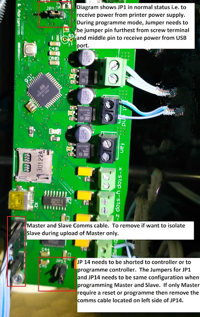
Jumper JP1 to receive only USB power. Jumper the pin near the edge without terminals and middle pin.
Jumper JP14 to reset controller. Leave JP1 and JP14 in this configuration until programme successfully uploaded from IDE.
Check for power from USB, LED will flash after 10 sec upon a connection with PC USB.
Tools > Serial Port > Com 3
//IDE will show Serial Port to be active//
Process to Upload and Check Content to EEPROM
1) Launch Pronterface > "Connect" > type G-code "M502" and "M500"
2) Turn off Power and Configure JP1 and JP14 for firmware upload.
3) Remove Comms link to Slave
4) Plug USB to PC, Check for connectivity to Sanguino PCB thru Arduino IDE
5) Compile and Upload Marlin thru Arduino IDE. Configure JP1 and JP14 for normal operation
6) Power up
7) Check if values of new configuration and values has successfully been retained. Type "M501" or "M503" to check values have changed. See Specimen Results below.
SENDING:M501
Firmware version: V10, EEPROM version: V10
ok p:12.00 i:2.20 d:80.00 w:125
echo:Stored settings retreived:
echo:Steps per unit:
echo: M92 X92.63 Y92.63 Z4000.00 E660.00
echo:Maximum feedrates (mm/s):
echo: M203 X300.00 Y300.00 Z3.00 E45.00
echo:Maximum Acceleration (mm/s2):
echo: M201 X800 Y800 Z30 E250
echo:Acceleration: S=acceleration, T=retract acceleration
echo: M204 S1000.00 T1000.00
echo:Advanced variables: S=Min feedrate (mm/s), T=Min travel feedrate (mm/s), B=minimum segment time (ms), X=maximum xY jerk (mm/s), Z=maximum Z jerk (mm/s)
echo: M205 S0.00 T0.00 B20000 X15.00 Z0.40 E15.00
echo: M206 X0.00 Y0.00 Z0.00 // PHA Offset not set yet.
echo:PID settings:
echo: M301 H1 P12.00 I2.20 D80.00 W125.00
M301 H2 P12.00 I2.20 D80.00 W125.00
M301 H3 P12.00 I2.20 D80.00 W125.00
FPU Enabled no
Axis 0 max: 210.00 Axis 1 max: 210.00 Axis 2 max: 140.00
Bed/extruder 0 beta: 3988.00 resistor: 4700.00 thermistor: 10000.00 inf: 0.02
Bed/extruder 1 beta: 4138.00 resistor: 4700.00 thermistor: 99999.91 inf: 0.09
Bed/extruder 2 beta: 273.00 resistor: 273.00 thermistor: 682.06 inf: 273.00
Bed/extruder 3 beta: 273.00 resistor: 273.00 thermistor: 682.06 inf: 273.00
Extruder: 0 dX: 0.00 dY: 0.00 dZ: 0.00 standby temp: 0.00 operating temp: 0.00
Extruder: 1 dX: 0.00 dY: 0.00 dZ: 0.00 standby temp: 0.00 operating temp: 0.00 //Second HE offset not set yet
Extruder: 2 dX: 0.00 dY: 0.00 dZ: 0.00 standby temp: 0.00 operating temp: 0.00 // Third HE offset not set yet
Process to Offset First HotEnd Origin
1) Test Movement of Print Head Assembly, Print Head Assembly (PHA) will consist of 1 or more HotEnd(s).
Command
G1 X1 Y1 F5000 // Move PHA to Home
G1 X40 Y0 // Move PHA by 40mm, First HE1 (T0) will come close to end of print bed.
G1 X100 Y100 // Move PHA, T0 to posit in middle of print bed.
2) Set the values to offset of PHA relative to Home position
M206 X-42 Y0 F5000 // Offset PHA by 42mm with respect to Home, this should bring the T0 to the corner of print bed.
M500 // Save values into EEPROM
3) Check if values are retained in EEPROM
SENDING:M503
echo:Steps per unit:
echo: M92 X92.63 Y92.63 Z4000.00 E660.00
echo:Maximum feedrates (mm/s):
echo: M203 X300.00 Y300.00 Z3.00 E45.00
echo:Maximum Acceleration (mm/s2):
echo: M201 X800 Y800 Z30 E250
echo:Acceleration: S=acceleration, T=retract acceleration
echo: M204 S1000.00 T1000.00
echo:Advanced variables: S=Min feedrate (mm/s), T=Min travel feedrate (mm/s), B=minimum segment time (ms), X=maximum xY jerk (mm/s), Z=maximum Z jerk (mm/s)
echo: M205 S0.00 T0.00 B20000 X15.00 Z0.40 E15.00
echo: M206 X-40.00 Y0.00 Z0.00 // PHA configured to offset by 40mm to start as G1 X0 Y0.
echo:PID settings:
echo: M301 H1 P12.00 I2.20 D80.00 W125.00
M301 H2 P12.00 I2.20 D80.00 W125.00
M301 H3 P12.00 I2.20 D80.00 W125.00
FPU Enabled no
Axis 0 max: 210.00 Axis 1 max: 210.00 Axis 2 max: 140.00
Bed/extruder 0 beta: 3988.00 resistor: 4700.00 thermistor: 10000.00 inf: 0.02
Bed/extruder 1 beta: 4138.00 resistor: 4700.00 thermistor: 99999.91 inf: 0.09
Bed/extruder 2 beta: 4138.00 resistor: 4700.00 thermistor: 95891.63 inf: 0.09
Bed/extruder 3 beta: 4138.00 resistor: 4700.00 thermistor: 95891.63 inf: 0.09
Extruder: 0 dX: 0.00 dY: 0.00 dZ: 0.00 standby temp: 150.00 operating temp: 200.00
Extruder: 1 dX: -42.40 dY: -0.18 dZ: 0.00 standby temp: 150.00 operating temp: 200.00 // HE2 (T1) offset by -42.40mm wrt to HE1
Extruder: 2 dX: -42.55 dY: -33.50 dZ: 0.00 standby temp: 150.00 operating temp: 200.00 // HE3 (T2) offset by -42.55mm wrt to HE1
Objective
To programme Marlin 1.0.7 onto a Melzi Sanguino w/ATMega 1284P 16 MHz board so that it will operate a Mendel Tricolour built 2013/2014.
New boards has since been released to replace the Melzi Sanguino however this microcontroller is still usable on the Mendel Tricolour Reprap 3D printer and hence used for educational purposes.
Tools
1x PC loaded with Arduino IDE and Marlin files for Mendel Tricolour,
2x Sanguino w/ATMega 1284P 16 MHz chip set and board (Tricolour has a Master and Slave board).
1x USB cable
Configuration for Arduino IDE
Files > Open > Marlin Multicolour files
//All files including library files will be opened e.g. xxx.h//
Tools > Board > Sanguino w/ATmega1284p 16MHz
Tools > Programmer > AVRISP MkII
Configuration for Sanguino Board to Reset and Programme
Jumper JP1 to receive only USB power. Jumper the pin near the edge without terminals and middle pin.
Jumper JP14 to reset controller. Leave JP1 and JP14 in this configuration until programme successfully uploaded from IDE.
 |
| Location of Pins and Connectors to Jumper or Remove during a Reset or for Programming Controller |
Tools > Serial Port > Com 3
//IDE will show Serial Port to be active//
Process to Upload and Check Content to EEPROM
1) Launch Pronterface > "Connect" > type G-code "M502" and "M500"
2) Turn off Power and Configure JP1 and JP14 for firmware upload.
3) Remove Comms link to Slave
4) Plug USB to PC, Check for connectivity to Sanguino PCB thru Arduino IDE
5) Compile and Upload Marlin thru Arduino IDE. Configure JP1 and JP14 for normal operation
6) Power up
7) Check if values of new configuration and values has successfully been retained. Type "M501" or "M503" to check values have changed. See Specimen Results below.
SENDING:M501
Firmware version: V10, EEPROM version: V10
ok p:12.00 i:2.20 d:80.00 w:125
echo:Stored settings retreived:
echo:Steps per unit:
echo: M92 X92.63 Y92.63 Z4000.00 E660.00
echo:Maximum feedrates (mm/s):
echo: M203 X300.00 Y300.00 Z3.00 E45.00
echo:Maximum Acceleration (mm/s2):
echo: M201 X800 Y800 Z30 E250
echo:Acceleration: S=acceleration, T=retract acceleration
echo: M204 S1000.00 T1000.00
echo:Advanced variables: S=Min feedrate (mm/s), T=Min travel feedrate (mm/s), B=minimum segment time (ms), X=maximum xY jerk (mm/s), Z=maximum Z jerk (mm/s)
echo: M205 S0.00 T0.00 B20000 X15.00 Z0.40 E15.00
echo: M206 X0.00 Y0.00 Z0.00 // PHA Offset not set yet.
echo:PID settings:
echo: M301 H1 P12.00 I2.20 D80.00 W125.00
M301 H2 P12.00 I2.20 D80.00 W125.00
M301 H3 P12.00 I2.20 D80.00 W125.00
FPU Enabled no
Axis 0 max: 210.00 Axis 1 max: 210.00 Axis 2 max: 140.00
Bed/extruder 0 beta: 3988.00 resistor: 4700.00 thermistor: 10000.00 inf: 0.02
Bed/extruder 1 beta: 4138.00 resistor: 4700.00 thermistor: 99999.91 inf: 0.09
Bed/extruder 2 beta: 273.00 resistor: 273.00 thermistor: 682.06 inf: 273.00
Bed/extruder 3 beta: 273.00 resistor: 273.00 thermistor: 682.06 inf: 273.00
Extruder: 0 dX: 0.00 dY: 0.00 dZ: 0.00 standby temp: 0.00 operating temp: 0.00
Extruder: 1 dX: 0.00 dY: 0.00 dZ: 0.00 standby temp: 0.00 operating temp: 0.00 //Second HE offset not set yet
Extruder: 2 dX: 0.00 dY: 0.00 dZ: 0.00 standby temp: 0.00 operating temp: 0.00 // Third HE offset not set yet
1) Test Movement of Print Head Assembly, Print Head Assembly (PHA) will consist of 1 or more HotEnd(s).
Command
G1 X1 Y1 F5000 // Move PHA to Home
G1 X40 Y0 // Move PHA by 40mm, First HE1 (T0) will come close to end of print bed.
G1 X100 Y100 // Move PHA, T0 to posit in middle of print bed.
2) Set the values to offset of PHA relative to Home position
M206 X-42 Y0 F5000 // Offset PHA by 42mm with respect to Home, this should bring the T0 to the corner of print bed.
M500 // Save values into EEPROM
3) Check if values are retained in EEPROM
SENDING:M503
echo:Steps per unit:
echo: M92 X92.63 Y92.63 Z4000.00 E660.00
echo:Maximum feedrates (mm/s):
echo: M203 X300.00 Y300.00 Z3.00 E45.00
echo:Maximum Acceleration (mm/s2):
echo: M201 X800 Y800 Z30 E250
echo:Acceleration: S=acceleration, T=retract acceleration
echo: M204 S1000.00 T1000.00
echo:Advanced variables: S=Min feedrate (mm/s), T=Min travel feedrate (mm/s), B=minimum segment time (ms), X=maximum xY jerk (mm/s), Z=maximum Z jerk (mm/s)
echo: M205 S0.00 T0.00 B20000 X15.00 Z0.40 E15.00
echo: M206 X-40.00 Y0.00 Z0.00 // PHA configured to offset by 40mm to start as G1 X0 Y0.
echo:PID settings:
echo: M301 H1 P12.00 I2.20 D80.00 W125.00
M301 H2 P12.00 I2.20 D80.00 W125.00
M301 H3 P12.00 I2.20 D80.00 W125.00
FPU Enabled no
Axis 0 max: 210.00 Axis 1 max: 210.00 Axis 2 max: 140.00
Bed/extruder 0 beta: 3988.00 resistor: 4700.00 thermistor: 10000.00 inf: 0.02
Bed/extruder 1 beta: 4138.00 resistor: 4700.00 thermistor: 99999.91 inf: 0.09
Bed/extruder 2 beta: 4138.00 resistor: 4700.00 thermistor: 95891.63 inf: 0.09
Bed/extruder 3 beta: 4138.00 resistor: 4700.00 thermistor: 95891.63 inf: 0.09
Extruder: 0 dX: 0.00 dY: 0.00 dZ: 0.00 standby temp: 150.00 operating temp: 200.00
Extruder: 1 dX: -42.40 dY: -0.18 dZ: 0.00 standby temp: 150.00 operating temp: 200.00 // HE2 (T1) offset by -42.40mm wrt to HE1
Extruder: 2 dX: -42.55 dY: -33.50 dZ: 0.00 standby temp: 150.00 operating temp: 200.00 // HE3 (T2) offset by -42.55mm wrt to HE1


Comments